
- Arduino analogwrite set to 0 how to#
- Arduino analogwrite set to 0 code#
- Arduino analogwrite set to 0 free#
So once again software artifacts cause zero to not be zero and us poor hardware guys have to figure out how to work around it or maybe ignore it, it's just 1/2% error. I'm sure there there are other lessons here but I'll let the group take in what I found and see if they have comments.

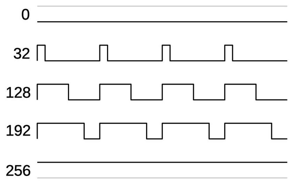
Beginners are frequently putting a voltmeter on a PWM pin and expecting something other then what is really happening. They probably should not have named the function "analogwrite" as that implies attributes that are not true for a digital PWM signal. Lastly I put a standard red led on pin 5, 150 ohm resistor to ground and ran the Reefer's program again and yes indeed even at the 'zero' output portion of the program there is a dim glow that can clearly be seen.Ī digital multimeter is not the proper instrument to troubleshoot PWM outputs, a scope is best. I measured 8 usec when at 1% duty so the error is only seen at duty cycle = to 0 and does not seem to effect higher percentage values. When the duty cycle is set to 50, the PWM signal approximates to 2.5V. When the duty cycle is set to 100, the PWM signal approximates to 5V. The amplitude of the PWM signal generated on Arduino is 5V.
Arduino analogwrite set to 0 code#
I went ahead and made the code output a duty % of one to see if the error is cumulative or just a zero offset error. The analog output from the PWM pin can be altered by changing the duty cycle of the PWM signal. So there is some timer interaction on Pin 4 that cause a loss of a true zero output that results in a 1/2% duty cycle output when it should be at 0% duty output. Bump the code up to duty cycle 1% and see a 8 usec positive pulse. At duty %0 duty there is no positive pulses to be seen, just flat-line zero volts. Move the code to pin 11 and scope pin 11 output. What is that 4 usec positive leading pulse doing there, during what should be a 0% duty cycle? Ran the Reefer's code and checked out pin 5 switching. I see the point, no need to go into it, no fear of otherwise wrecking it accidentally. The first is our pin, and the second is any value between 0 and 255. analogWrite sets the pin to have an oscillating value which has a pulse length based of the duty cycle specified as the second parameter.
Arduino analogwrite set to 0 free#
So I did what any good hardware guy would do, break out the Tek scope and try and recreate the symptom. OK, so you want to have a function that you can stick into the original code, in your example at the end of the free running unblocked loop() that can read back the value the rest of the (otherwise unmolested not changed) program analogWrote. There are two parameters to analogWrite(). digitalWrite sets the pin to an high or low value that remains at exactly that value until digitalWrite is called for that pin again. I am trying to learn why an LED is brighter when I use digitalWrite than the same LED when using analogWrite. I just got a Getting Started with Arduino Kit and have been going through the book Getting Started with Arduino that came with the kit.

Well this is one of those threads where when you first start to read it one might think it's a all too frequent wiring or coding mistake type situation, However as others brought nuggets of info and suggestions it got more interesting. I am new to electronics and which means I am new to Arduino as well.


 0 kommentar(er)
